

Tactical Graphics
A Tactical Graphic is a graphic defined by a symbol set. A graphic can be an icon that is drawn a geographic position, a vector graphic that is positioned using one or more control points, or a line or polygon that is styled according to the symbol set’s specification. This guide covers tactical graphics belonging to the U.S. Department of Defense’s Common Warfighting Symbology set, MIL-STD-2525. Not all 2525C graphics are supported in WorldWind. See Tactical Graphic Status for a list of supported graphics.
 The tactical graphics Java Web Start demo showcases how tactical graphics appear and behave in a WorldWind based application.
The Tactical Graphics Demo code can be found in the GitHub repository.
Overview
This guide shows how to use tactical graphics in your application, and is organized into in four sections:
Construction
Each graphic within a symbol set has a unique identifier. Tactical graphics are typically created by an instance of TacticalGraphicFactory. The factory interface defines several methods:
interface TacticalGraphicFactory
{
    TacticalGraphic createGraphic(String symbolId, Iterable<? extends Position> positions,
        AVList modifiers);

    TacticalPoint createPoint(String symbolId, Position position, AVList modifiers);

    TacticalCircle createCircle(String symbolId, Position center, double radius,
        AVList modifiers);

    TacticalQuad createQuad(String symbolId, Iterable<? extends Position> positions,
        AVList modifiers);

    TacticalRoute createRoute(String symbolId,
        Iterable<? extends TacticalPoint> controlPoints, AVList modifiers);
}
createGraphic is the most general of these methods. It takes three parameters:
- symbolId—A string identifier that indicates which graphic in the symbol set to create. The format of this identifier depends on the symbol set. For example, a MIL-STD-2525 Symbol Identification Code (SIDC) is a string of 15 characters.
- position—The geographic position (or positions) at which to place the graphic. Some graphics require only one position; others require multiple positions.
- modifiers (optional)—A parameter list that specifies text and graphic modifiers. This parameter may be null if you do not wish to specify modifiers.
The other creation methods (createPoint, createCircle, createQuad, and createRoute) are provided for convenience to create common types of graphics:
- createPoint-Create a graphic positioned by only one control point.
- createCircle-Create a graphic positioned by a center point and radius.
- createQuad-Create a quadrilateral with length and width.
- createRoute-Create a graphic composed of point graphics connected by lines, such as the Minimum Risk Route defined by MIL-STD-2525C.
In order to create a graphic you will need to instantiate the appropriate factory for the symbol set that you intend to use. In this case we’re using MIL-STD-2525, so we’ll use the MilStd2525GraphicFactory.
The TacticalGraphic interface provides access to settings common to all tactical graphics. It’s sub-interfaces (TacticalPoint, TacticalCircle, TacticalQuad, and TacticalRoute) provide more specific accessors for different types of graphic. TacticalGraphic extends the Renderable interface, so you can add a TacticalGraphic directly to a RenderableLayer.
Here’s an example of how to create a graphic and add it to a layer:
// Create a graphic factory for MIL-STD-2525
TacticalGraphicFactory factory = new MilStd2525GraphicFactory();
// Specify the control points for the line
List&lt;Position&gt; positions = Arrays.asList(
Position.fromDegrees(34.7327, -117.8347, 0),
Position.fromDegrees(34.7328, -117.7305, 0));
// Specify a text modifier
AVList modifiers = new AVListImpl();
modifiers.setValue(SymbologyConstants.UNIQUE_DESIGNATION, &quot;Alpha&quot;);
// Create a graphic for a MIL-STD-2525 hostile phase line. The first argument is the
// symbol identification code (SIDC) that identifies the type of graphic to create.
TacticalGraphic graphic = factory.createGraphic(&quot;GHGAGLP----AUSX&quot;, positions, modifiers);
// Create a renderable layer to display the tactical graphic. This example adds only a
// single graphic, but many graphics can be added to a single layer.
RenderableLayer layer = new RenderableLayer();
layer.addRenderable(graphic);
// Add the layer to the WorldWindow's model and request that the layer redraw itself.
// The WorldWindow draws the graphic on the globe at the specified position. Interactions
// between the graphic and the cursor are returned in the WorldWindow's picked object
// list, and reported to the WorldWindow's select listeners.
WorldWindow wwd = ... // A reference to your application's WorldWindow instance.
wwd.getModel().getLayers().add(layer);
wwd.redraw();
Here’s the graphic that is created by the code above:
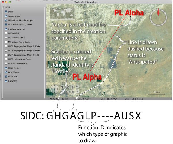
The symbol identifier (GHGAGLP—-AUSX) tells the factory what type of graphic to create, and how the graphic should be styled. The Function ID (GLP) indicates that our graphic is a Phase Line. Character 2 (H) indicates that the graphic is for a Hostile entity, so it is drawn in red. Character 4 (A) indicates that the object is anticipated, rather than present, so it is drawn with a dashed line.
Most graphics also support modifiers which are not part of the symbol identifier. In the example above we added a text modifier of “Alpha” to identify our phase line. These parameters can be specified using a parameter list when the TacticalGraphic is created. See Modifiers for more information on setting modifiers.
Position
Each tactical graphic is positioned by one or more control points. How many points are required depends on the type of graphic. A point graphic will only require one position. A more complex shape may require three or four, and a line or area may allow any number.
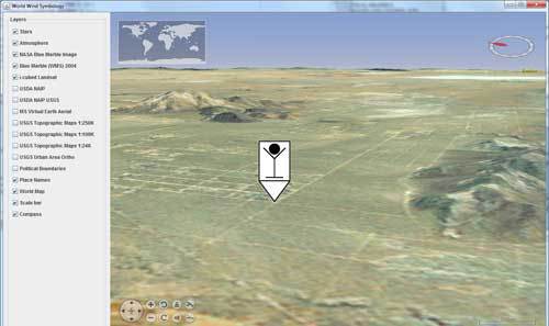
Let’s look at how to create a point graphic for a Downed Aircrew Pickup Point (G*GPAPD—****X). Because we have only one control point, we use the createPoint factory method:
// We need to create one Position object
Position position = Position.fromDegrees(34.9362, -118.2559, 0);
//And then create the graphic
TacticalGraphic graphic = factory.createPoint(&quot;GFGPAPD----AUSX&quot;, position, null);
The result is an icon drawn at the specified position:
More complicated graphics will require more control points. MIL-STD-2525 defines a template for each tactical graphic. Each template identifies how many control points are required, and how the points are interpreted. The TacticalGraphicFactory accepts a list of Position objects, which identify the control points in the same order as in the specification.
For example, consider the Ambush graphic (G*GPSLA—****X) from 2525C. The template indicates that the graphic requires three control points:
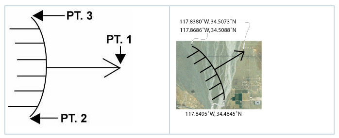
Suppose that we want to position the graphic as shown above.
// We need to create a position list that specifies the three control points in order
List&lt;Position&gt; positions = Arrays.asList(
Position.fromDegrees(34.5073, -117.8380, 0), // PT. 1
Position.fromDegrees(34.4845, -117.8495, 0), // PT. 2
Position.fromDegrees(34.8686, -117.5088, 0)); // PT. 3
// And now we can create the graphic
TacticalGraphic graphic = factory.createGraphic(&quot;GFGPSLA----AUSX&quot;, positions, null);
An application can change the location of a graphic after the graphic has been created using the TacticalGraphic interface.
List<Position> newPositions = ... // Get updated positions
tacticalGraphic.setPositions(newPositions);
Modifiers
Text and graphic modifiers can be specified in the parameter list when a graphic is created, or using the setters on the TacticalGraphic interface after the graphic has been created.
Let’s look at how to create a Biological Hazard graphic with some text modifiers. MIL-STD-2525 defines this template for the Biological graphic:
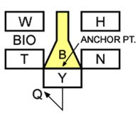
The boxed letters correspond to modifiers:
| Symbol | Meaning |
|---|---|
| W | Date/Time |
| H | Additional Information |
| T | Unique Designation |
| N | Identity Indicator (hostile or friendly) |
| Y | Position |
| Q | Direction Indicator |
We will set up a parameter list with the modifiers that we want to use:
AVList modifiers = new AVListImpl();
modifiers.setValue(SymbologyConstants.UNIQUE_DESIGNATION, &quot;X469&quot;); // Field T
modifiers.setValue(SymbologyConstants.DATE_TIME_GROUP, &quot;10095900ZJAN92&quot;); // Field W
modifiers.setValue(SymbologyConstants.ADDITIONAL_INFORMATION, &quot;Anthrax Suspected&quot;); // Field H
modifiers.setValue(SymbologyConstants.DIRECTION_OF_MOVEMENT, Angle.fromDegrees(30.0)); // Field Q
Position position = Position.fromDegrees(35.1026, -118.348, 0);
// Create the graphic with the parameter list
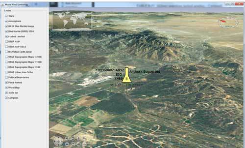
TacticalGraphic graphic = factory.createPoint(&quot;GHMPNEB----AUSX&quot;, position, modifiers);
The result is an icon surrounded by the modifiers that we specified:
A modifier can also be set (or changed) after the graphic is created by the setModifier method defined by the TacticalGraphic interface:
// Create the graphic
TacticalGraphic graphic = factory.createGraphic(&quot;GHMPNEB----AUSX&quot;, positions, null);
// Specify the modifier as a key-value pair
graphic.setModifier(SymbologyConstants.UNIQUE_DESIGNATION, &quot;Boston&quot;);
The set of possible modifiers depends on the symbol set. See MilStd2525TacticalGraphic for a list of modifiers supported by MIL-STD-2525C graphics.
Display Options
Setting Colors
By default, a tactical graphic is configured with attributes defined by the symbol specification. However, the attributes of a graphic can be customized using the TactialGraphicAttributes interface:
TacticalGraphic graphic = factory.createGraphic(&quot;GFGPSLA----AUSX&quot;, positions, null);
// Create a new attributes bundle. Any fields set in this bundle will override the default
// attributes. Fields that are left unset will not affect the defaults.
TacticalGraphicAttributes attributes = new BasicTacticalGraphicAttributes();
// Override the default color with green. Leave the other fields unset to retain other
// default values specified by the symbol set.
attributes.setOutlineMaterial(Material.GREEN);
graphic.setAttributes(attributes);
TacticalGraphicAttributes is used to override a graphic’s default attributes. MIL-STD-2525 determines most of a graphic’s attributes through the SIDC (friendly graphics default to black, hostile graphics default to red, etc.). Any fields in the attributes bundle that are set will override the defaults specified by the symbol set, while fields left unset will not affect the defaults. This allows an application to easily override a few fields without interfering with other defaults.
Positioning Modifiers
Sometimes an application will need to reposition an information label within a graphic. By default, labels are positioned according to the templates in MIL-STD-2525, but an application is free to override these defaults using the Offset class.
// Create a “Named Area of Interest” graphic
TacticalGraphic graphic = factory.createGraphic(&quot;GFGPSAN----AUSX&quot;, positions, null);
// Set the Unique Designation modifier
graphic.setModifier(SymbologyConstants.UNIQUE_DESIGNATION, &quot;(Unit ID)&quot;);
// Place the label above and to the right of the default location
Offset offset = new Offset(19d, 8d, AVKey.PIXELS, AVKey.PIXELS);
// Apply the label position
graphic.setLabelOffset(offset);
Visibility of Modifiers
The visibility of text and graphic modifiers can be controlled using the setShowModifiers method of TacticalGraphic. To disable an individual modifier, set its value to null.